Photo case study
Upper right premolars #14 & #15 with the Crown Down 2-drill protocol
Two adjacent maxillary premolar implants planned from CBCT and placed with the Crown Down cortical-first sequence. A photo case published by Dr. Alberto Miselli, DDS.

Case performed by
Dr. Alberto Miselli, DDS
Operating clinician, Venezuela. Case published on his clinical channel and reproduced here with the surgical sequence and commentary from his original post.
- Sites (FDI)
- #14 and #15
- Region
- Upper right premolars
- Implants
- 3.75 x 11.5 mm / 3.75 x 10.0 mm
- Protocol
- Crown Down 2-drill + bone collection
Two adjacent implants placed at the upper right first and second premolars, planned from CBCT and prepared with the Crown Down cortical-first drilling sequence. The case illustrates how the protocol handles two neighbouring sites in the same pass, and how the third bone-collection drill produces autogenous chips at biologic speed without a separate donor procedure.
The case comes from Dr. Alberto Miselli, DDS, who has been publishing his Crown Down cases on his clinical channel. Beyond the surgical sequence itself, Dr. Miselli uses this case to frame a biomechanical hypothesis about insertion torque: that by selectively reducing cortical interference first, the torque reading on the wrench better reflects what the medullary bone is actually offering, rather than adding up crestal compression on top of medullary support.
Photo essay
The surgical sequence, step by step
Every step below shows Dr. Miselli's original clinical imagery paired with a short technical note on what the Crown Down protocol is doing at that moment.
- STEP 01
Planning from CBCT
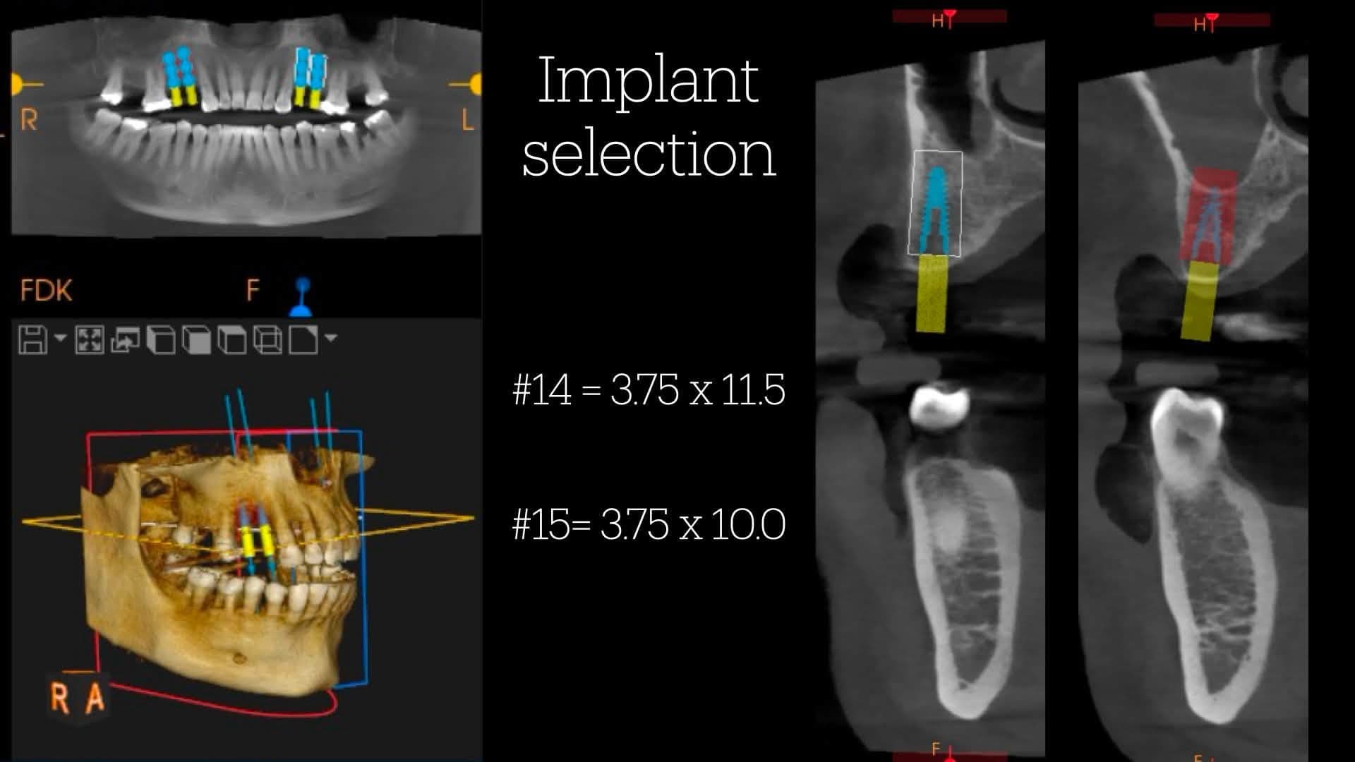
Two adjacent maxillary premolar sites were planned from CBCT with two implants: 3.75 x 11.5 mm at #14 and 3.75 x 10.0 mm at #15. The panoramic reconstruction and 3D model at the left confirm axial angulation and inter-implant spacing; the two right-hand sagittal slices show adequate bone volume at both sites with respect for the buccal plate.
- STEP 02
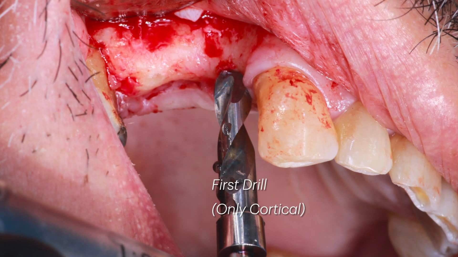
First drill - cortical only
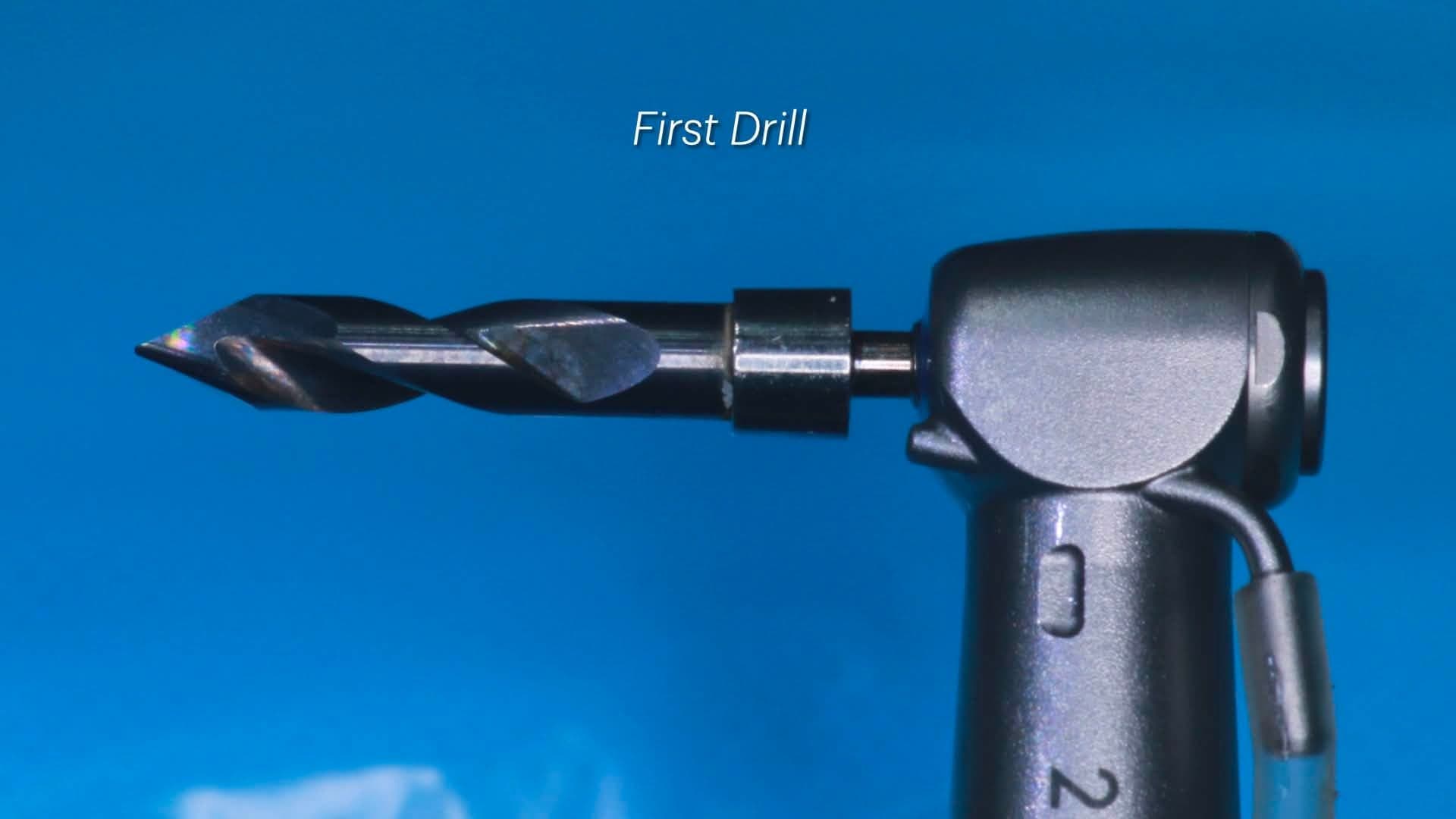
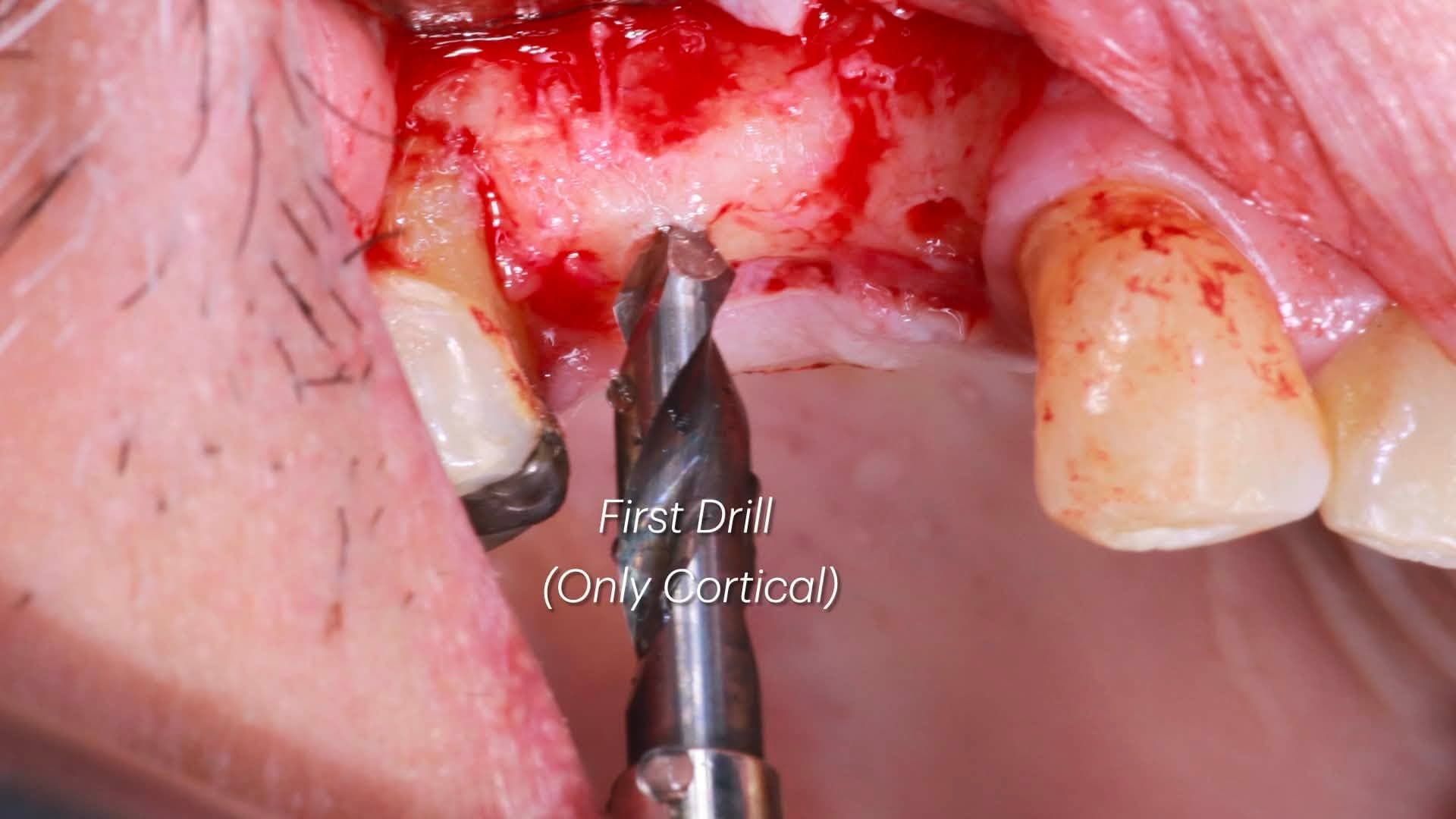
The Crown Down first drill is a solid tungsten carbide cortical drill matched to the target implant diameter. In this case it engages only the cortical plate, breaching the crest to the depth of the cortical layer and no further. Selectively reducing cortical interference first is the mechanical premise of the protocol: it prevents the crestal ring from dominating the eventual torque signature.
- STEP 03
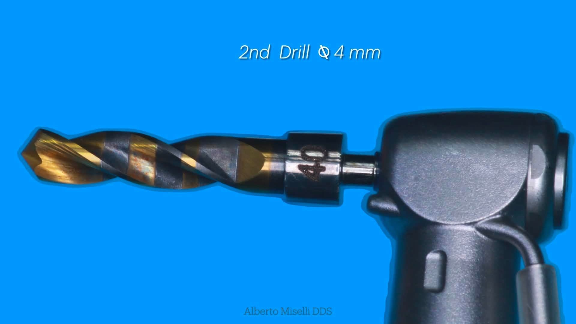
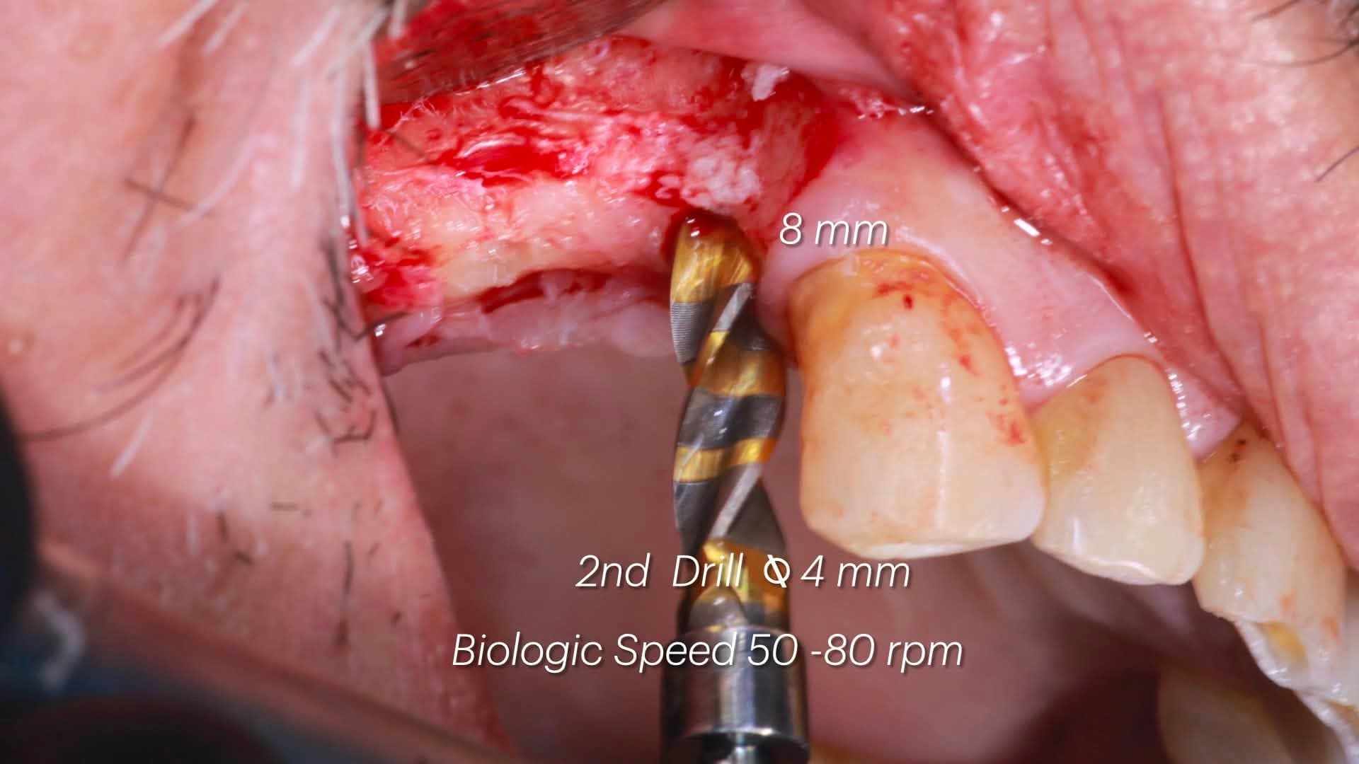
Second drill - trabecular Ø 4 mm
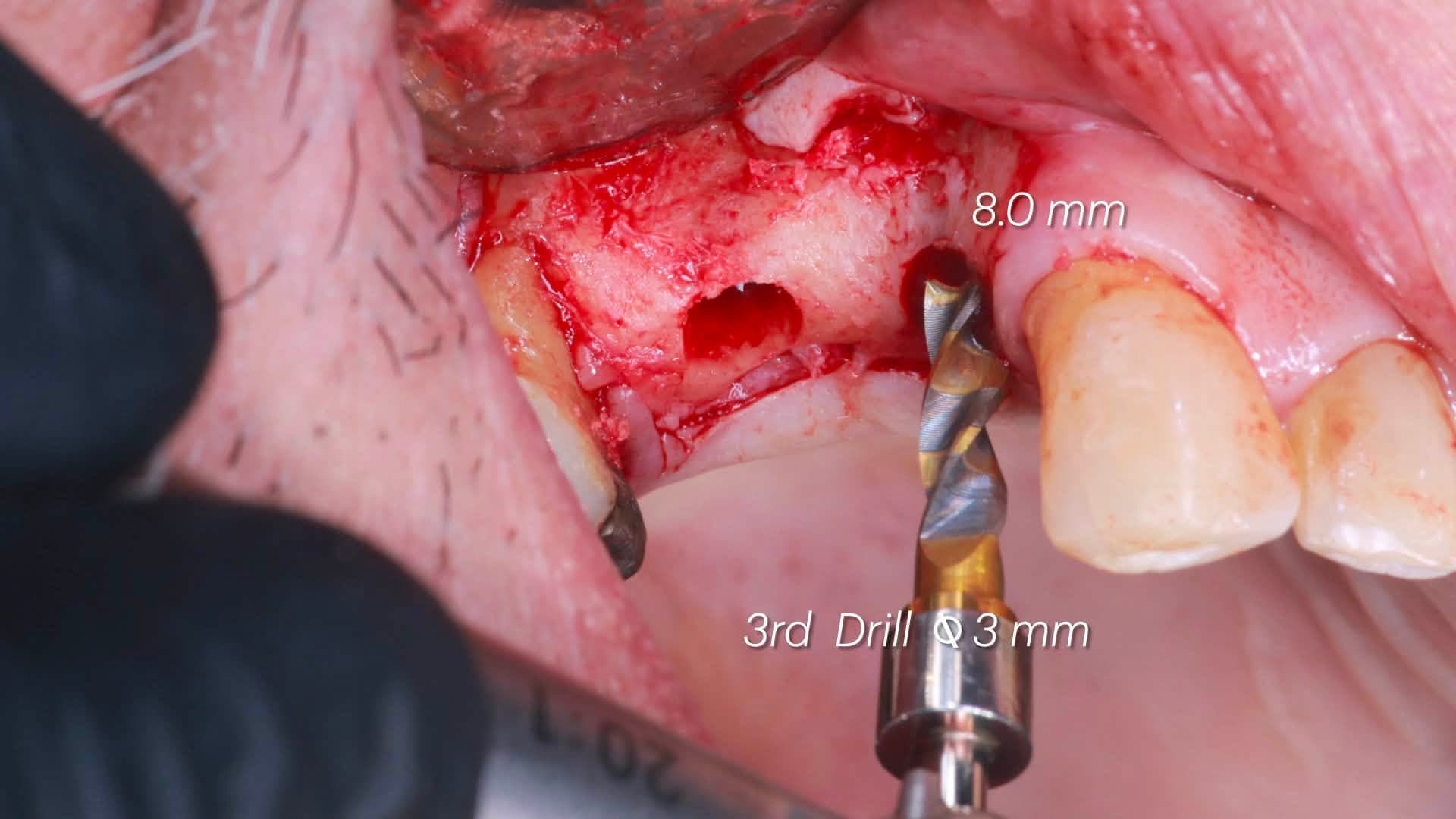
The second drill in the sequence extends the osteotomy through the medullary compartment at approximately 8 mm of depth. Because the cortical layer has already been dedicated its own pass, the second drill only engages trabecular bone - which behaves differently mechanically and preserves a wider tactile window on the handpiece.
- STEP 04
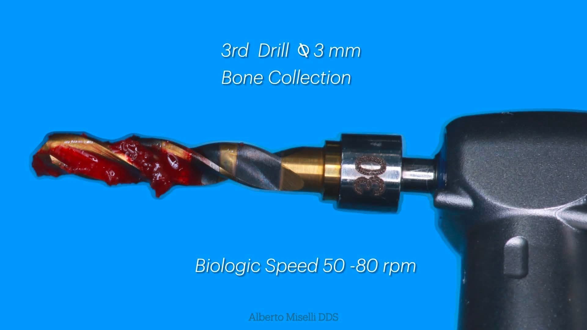
Third drill - Ø 3 mm bone collection at 50-80 rpm
A dedicated 3 mm drill is run slowly, at biologic speed (50-80 rpm), through the prepared site. Because Crown Down drills at low speed without continuous external irrigation, the bone particles produced during this pass stay in the site and on the flutes rather than being washed into the suction line. Those chips can be collected chairside and used as an autogenous graft in the same appointment.
- STEP 05
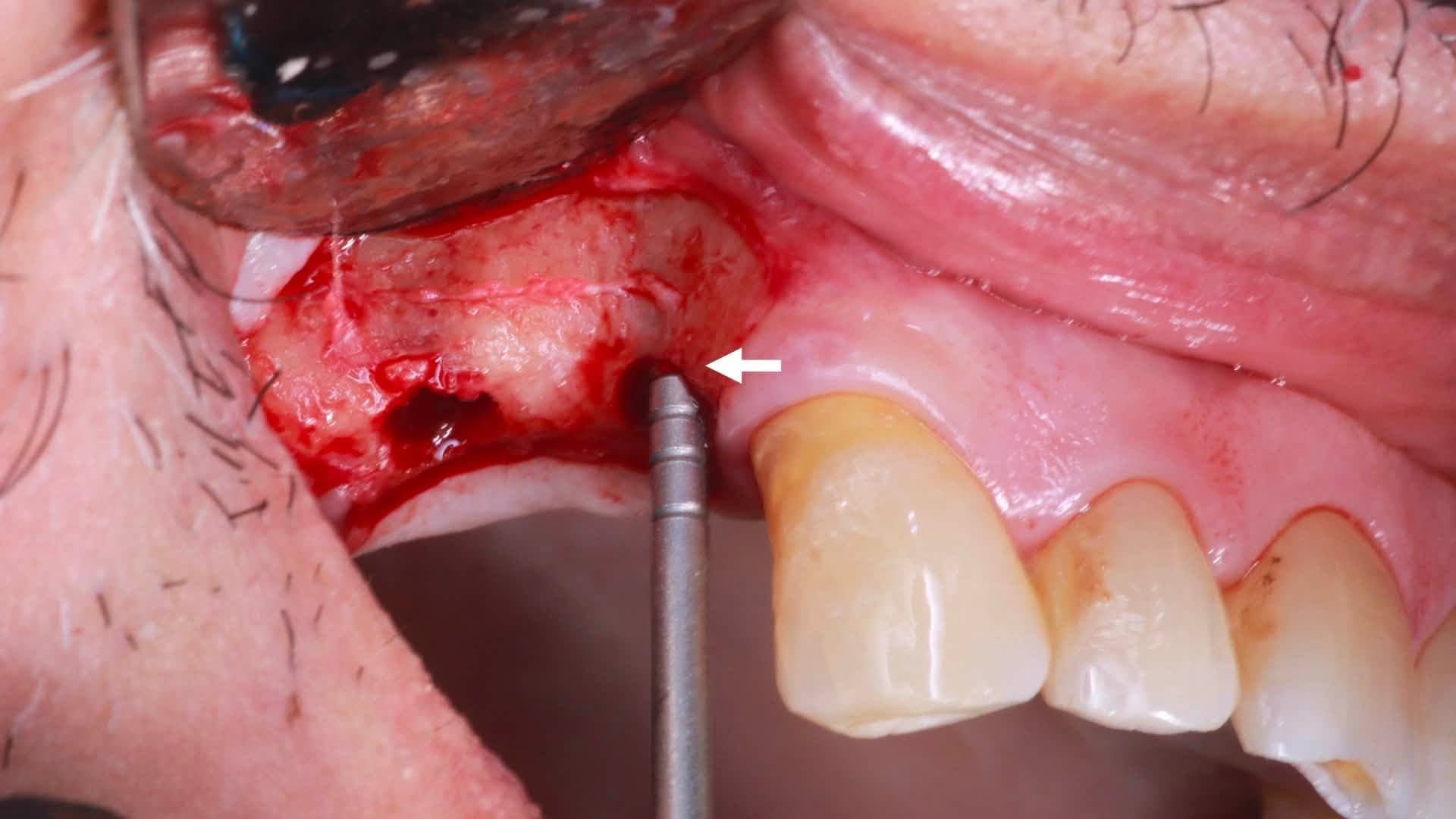
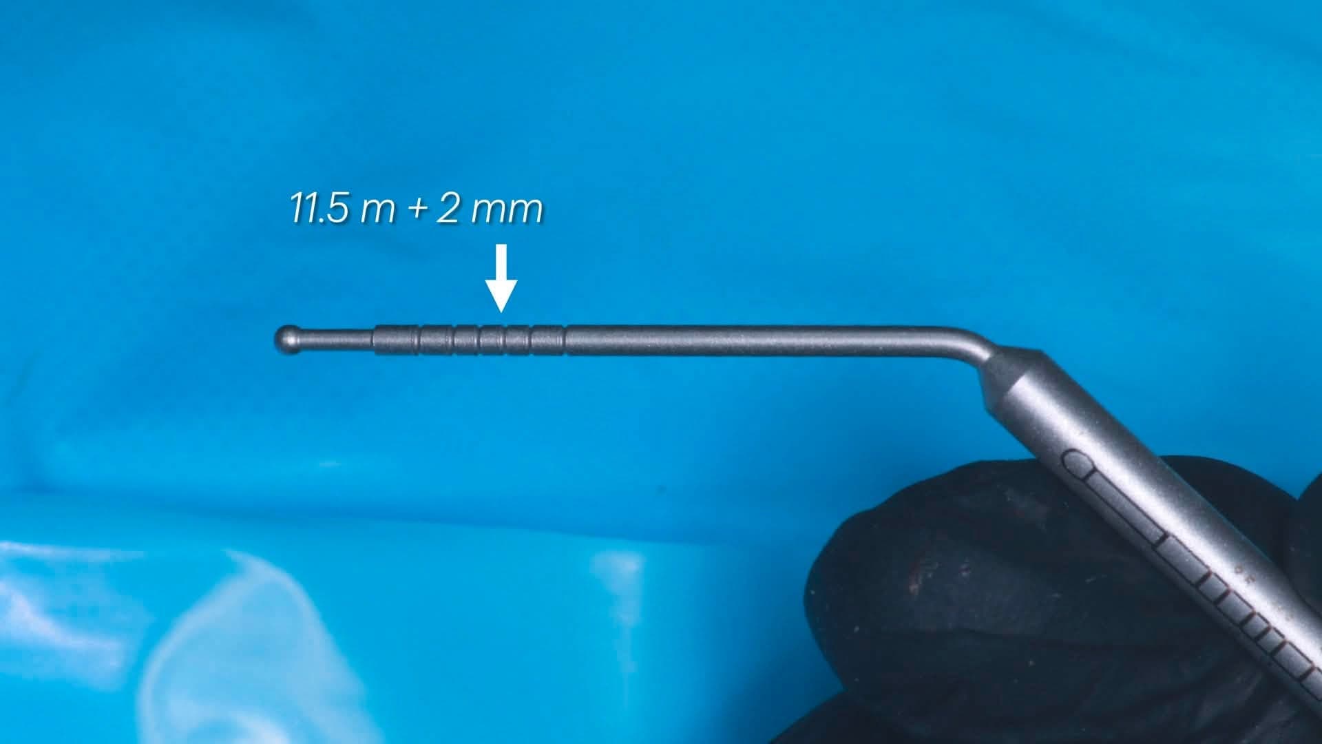
Osteotomy check and depth confirmation
Before switching from drilling to implant placement, the site is inspected and the depth is confirmed with a graduated probe. The reference shown here is 11.5 mm + 2 mm, which corresponds to the planned depth for the #14 implant plus a small safety margin.
- STEP 06
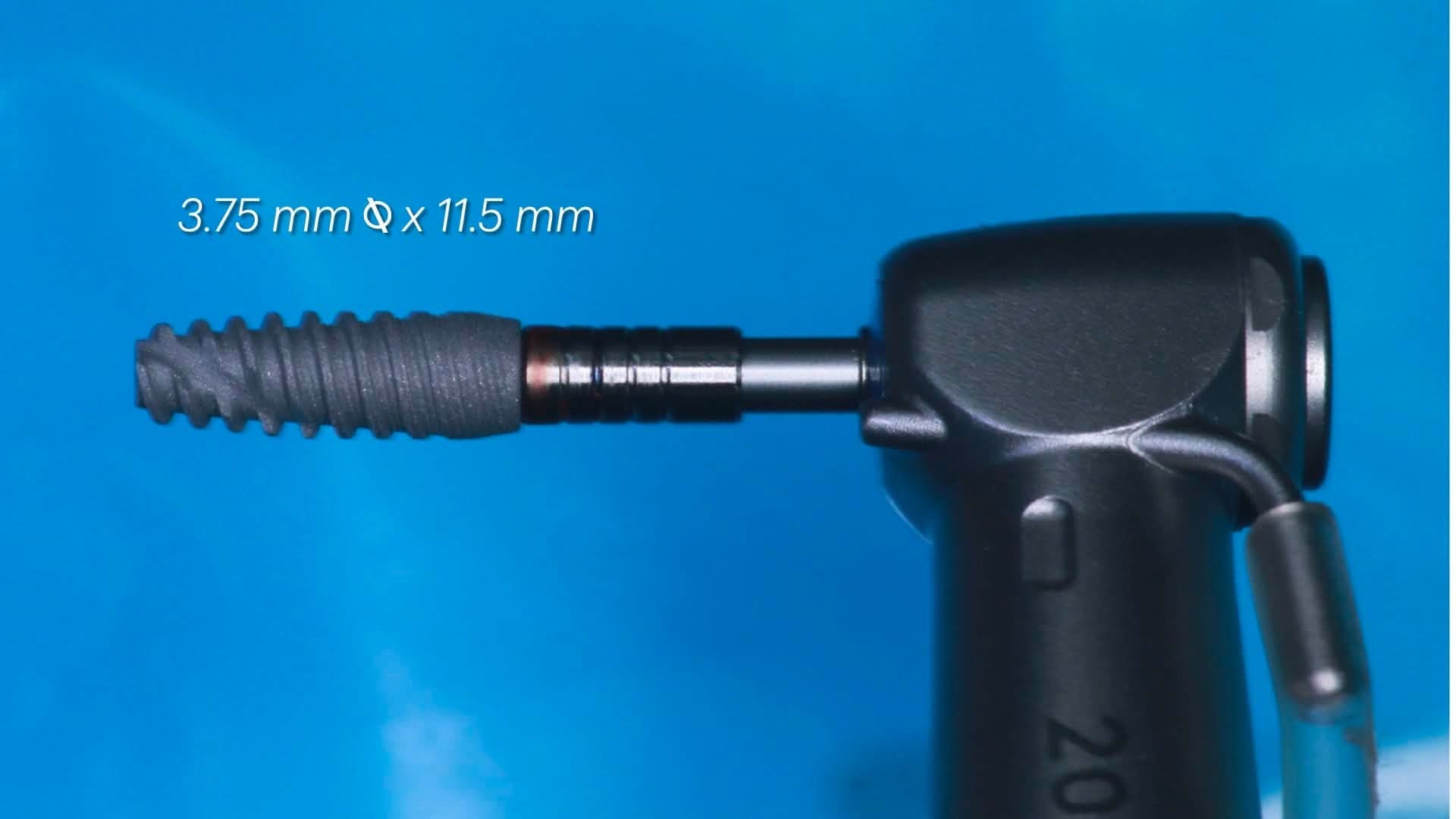
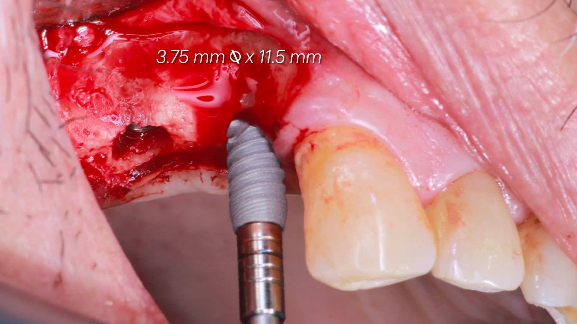
Implant #14 - 3.75 x 11.5 mm
The first implant is seated at the mesial site. Because the cortical ring has been decompressed by the initial cortical drill, the torque wrench reading during placement reflects primarily the medullary bone's contribution rather than crestal compression against a bone-tap-like preparation.
- STEP 07
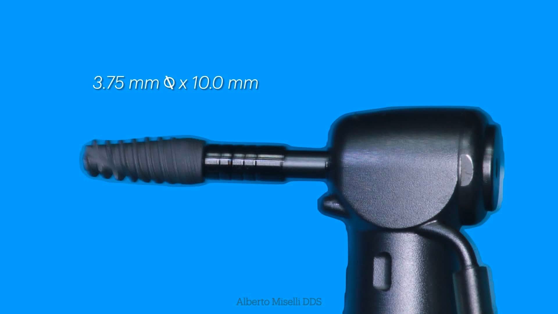
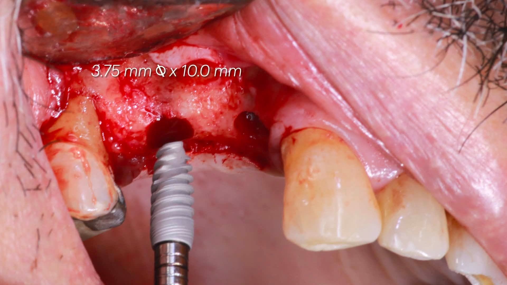
Implant #15 - 3.75 x 10.0 mm
The distal site receives a slightly shorter implant of the same diameter. Both implants are placed in the same visit and prepared with the identical 3-drill sequence, so the surgical rhythm and tactile feedback remain consistent between adjacent sites.
- STEP 08
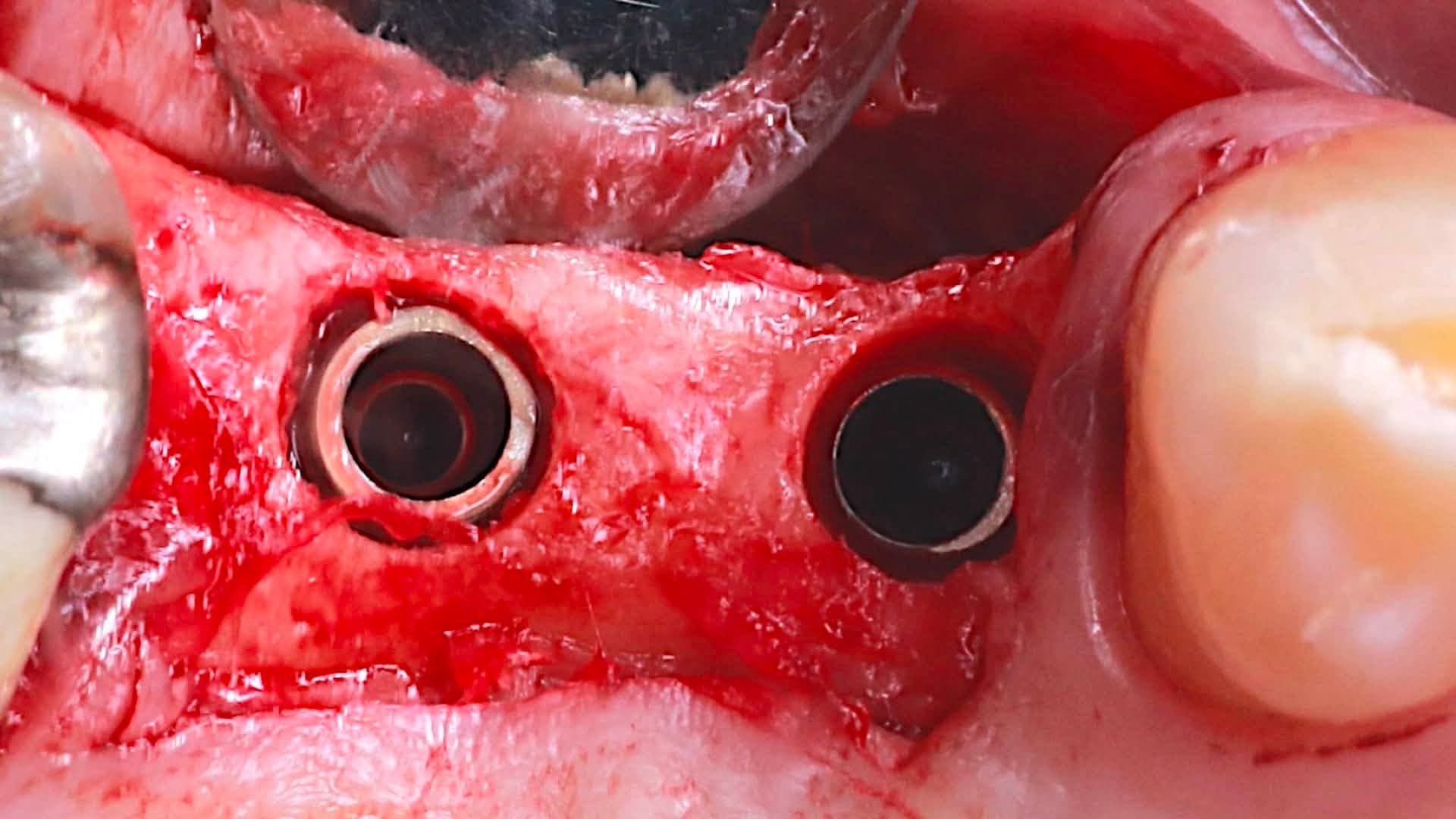
Both implants seated, cover screws in place
Occlusal view of the completed placement: two adjacent implants at #14 and #15 with cover screws, ready for closure. From here the case is followed with a post-operative periapical radiograph before releasing the tissue.
- STEP 09
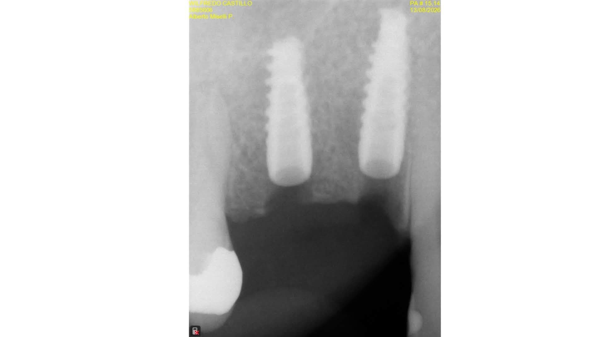
Post-operative periapical radiograph
Post-op periapical radiograph confirming both implants at planned depth and axial angulation, respecting the adjacent tooth roots and the sinus floor.
“This is one of the principles behind the Crown-Down technique: by selectively reducing cortical interference, insertion torque may better reflect the true mechanical contribution of the medullary bone while reducing excessive crestal compression. Same torque, different bone, different biology.”
Dr. Alberto Miselli, DDS
Operating clinician, Venezuela
The insertion-torque framing is presented by Dr. Miselli as a biomechanical hypothesis about the Crown-Down technique that requires further experimental validation. Individual clinical results will vary with anatomy, bone quality and technique.
Want to see the full technique background?
Read the 2-drill protocol for the sequence used in this case, or the sister case at #35 with autogenous bone harvesting for the same bone-collection principle in a single-site case.
Case questions and technique reference
Quick clinical answers dentists ask about this case and about the Crown Down 2-drill protocol it demonstrates.
Keep reading
Related reading
Explore related pages on the Crown Down dental implant drilling kit, protocol, and clinical science.
Protocol
The 2-Drill Implant Osteotomy Protocol
How drill #1 and drill #2 prepare the implant osteotomy in two steps.
Read moreCase: #25 & #26
Upper Left #25 & #26 - Dr. Diederich
A photo case from Dr. Henri Diederich, DDS (Luxembourg): two adjacent maxillary implants placed dry with the Crown Down 2-drill protocol, autogenous bone captured on the drill flutes.
Read moreClinical Cases
Crown Down Clinical Case Studies
Live implant surgery footage - different sites, different bone types, the same 2-drill Crown Down protocol.
Read more